Hardware for a Led Matrix Display and Led RGB Strip DIY Project
I decided to build a led matrix based display for my home office. So after quitting my job, I took the luxury of not looking for a new one. Instead, I began the fun packed adventure of do it yourself (DIY) electronics! As I will soon need to get a real job, I thought of blogging what I built, to hopefully inspire whoever may be interested in building something similar. Note: quitting your job is not a requirement! :)
I have played with Arduinos a bunch before. While they will always have a special place in my heart, I made the switch to using something much more powerful and cheaper: Raspberry Pi (aka RPI). With that, a big chunk of my project on the software side involved porting the Arduino based code to work under the RPI. I will talk more about that in the part 2 of this blog. For this portion, I will focus on the hardware I cobbled together and provide you with some pictures for setting the context.
For starters, let me begin with a list of the main components used, and then elaborate a little on each one.
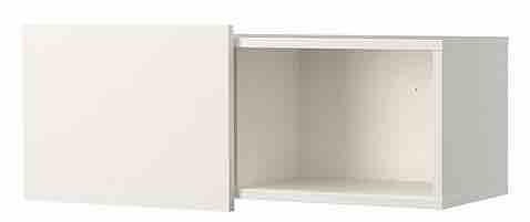
Ikea BRIMNES Wall Cabinet
http://www.ikea.com/kw/en/catalog/products/40218078/
BRIMNES Wall cabinet with sliding door, white -- KD 9
Article Number : 402.180.78
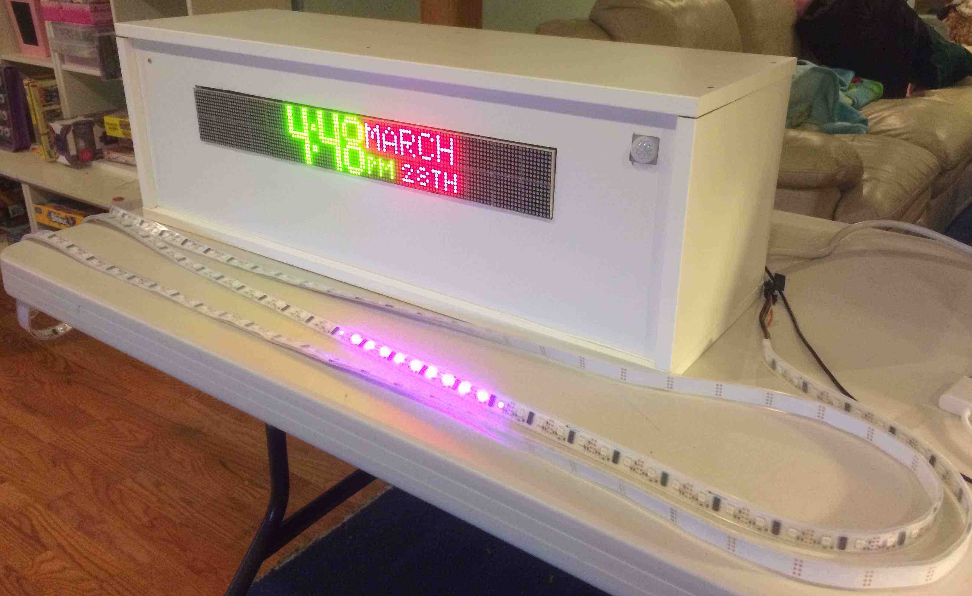
This is the structure I'm using for holding it all together. In order to attach the display and the sensors, my super duper wife helped me out by cutting a perfect rectangle out of the back of the cabinet. By swapping the sliding door with the back panel we can create a perfect front. The back piece is a lot slimmer, thus easier to cut. For doing the cutting, she used an oscillating tool like the DeWalt Oscillating saw DWE315K. Still, I think that with a cutting knife [and patience] one can do that job as well. The dimensions of the cutout for the display are 20 and 5/16, by 2 and 5/8 inches.
As you can see in the picture above, I used the holes that came with the back panel to hold the light and motion sensors. For the motion sensor, the squared cutout is 7/8th of an inch.
In the near future, we will tape around the edges to make the display and the panel seamless.
Led Strip (and power adapter)
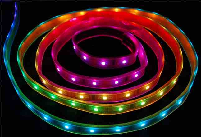
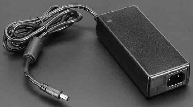
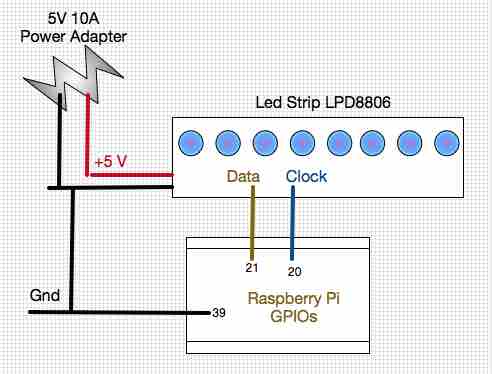
I plan on stretching a long and animated line of RGBs across the wall where the office clock will be located. For that, I got a 5 meter reel of the LPD8806 from Adafruit. To power that, I am using a 5 volts, 10 amp switching power supply. You can use a smaller -- or no -- strip, of course.
In order to control the strip with a RPI using c++, I did small tweaks to the code that Ladyada and PaintYourDragon wrote. More on that when we cover the software piece.
4x Bicolor Led Matrix Display (and power adapter)
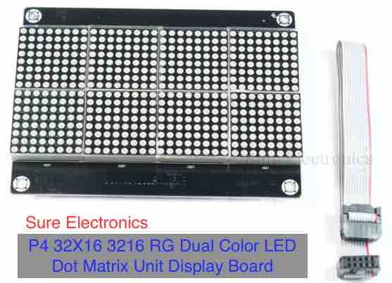
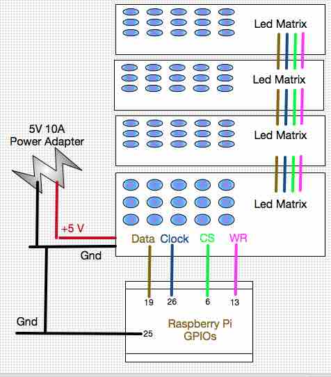
After considering a couple of options, I ended up using a daisy chain of four 32x16 bicolor displays, from Sure Electronics. I really liked the price of them on Ebay, which is a lot cheaper than the price in their official website. Go figure! Another reason that made me go for this display is the fact that I got it working with an Arduino in the past, so I have a good handle on porting that code to the RPI. More on that in the part 2 of this blog.
By the way, there is nothing magical about 4 here. You can can go as small as 1 and all that means is that you will get fewer pixels to play with. I will certainly not judge. ;)
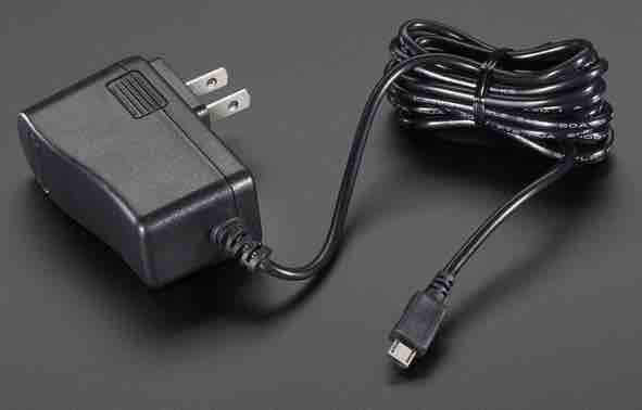
Just like the led strip, you will need to have a dedicated 5 volts power adapter to feed the led matrix. I started off by using a cheap-o adapter off of Ebay and that turned out to be a mistake. The thing was outputting more than 5 volts and I failed to notice that before destroying one of my matrix boards. @#$%#!!! :( I guess I'm lucky that only one was damaged; to look at it from the bright side. Anyways... what I use now is a VSK-S10-5UA, which can handle up to 2 amps. I bought that at Digi-Key. According to the matrix manual, the max usage of a single board is 1.37 amps, so I will likely run into trouble when attempting to light up all leds on 100% PWM duty cycle. A better idea may be to get a power adapter similar to the one used by the led strip. Thus, do what I say -- not what I do on that one. :)
Raspberry Pi and case (plus power adapter)
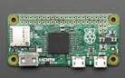
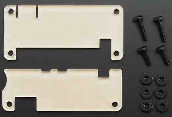
I think any model of the RPI can be used for this project. In this case, I am using the RPI zero because that is the cheapest and I was lucky enough to find one available at Adafruit. As I will talk about later on, I use a simple web server to handle rest-like calls and cause interesting things to occur. In order to better protect the RPI from my greasy fingers, I also bought a protector case for it.
Micro SD Memory Card
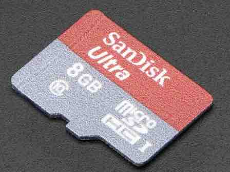
The card I'm using came as part of the kit that I bought at Adafruit. Its is 8Gb and made by Sandisk.
USB Hub
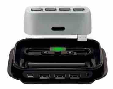
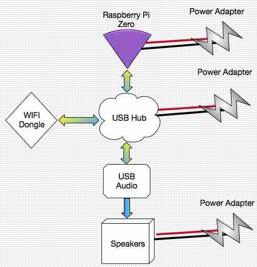
This is something you may only need when using a RPI zero. In my case, I had an old USB 2.0 hub from Belkin that works just fine. One good thing about the hub I'm using is that it has its own power supply, which makes it less taxing on the power used by the RPI.
WIFI Dongle

The wifi dongle I'm using can be bought at Adafruit as well. Since I'm using a RPI zero, I have it attached to the usb hub.
USB Audio Adapter
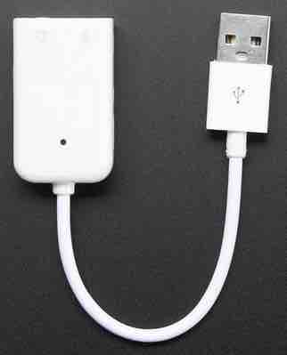
Another item that you would only need if you are using a RPI zero. This is also something you can get at Adafruit. There are other ways that Ladyada beautifully explains in regards to getting audio from RPI zero. I chose this path because it seemed the easiest for what I intend to do. To be honest, I'm yet to write the code that handles audio, but I think that should work. ;)
Audio Speakers

A simple set of speakers that hooks up to the USB based audio adapter or the RPI (if you are not using a RPI zero). I just purchased these from AmazonBasics for 14 bucks.
PIR Motion
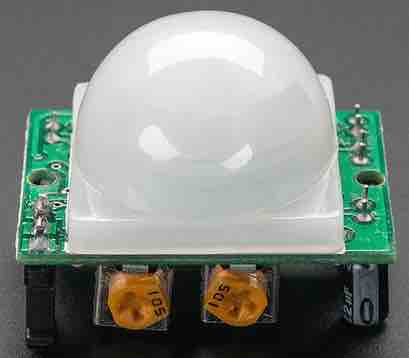
I wanted a way of detecting when there is nobody around, so the clock can go on power saver mode. For that, I attached a PIR motion sensor. Hooking it up is quite simple, as I will show down below.
Light Sensor
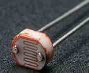
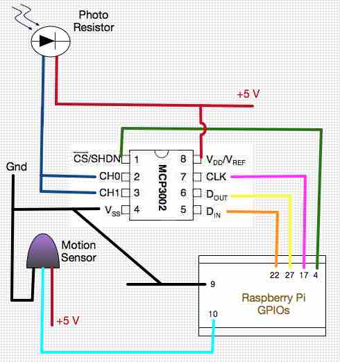
As yet another way of saving power, I wanted the ability to see how bright the room is, so I can adjust the intensity of the LEDs (aka PWM duty cycle). For that, I use a simple photo resistor. A caveat here is that the RPI does not have a native way of reading analog values, which is something needed to work with this sensor. Ladyada has an awesome video on youtube that talks about ways of working around this limitation. For the fun of it, I connected the photo resistor to an MCP3002, listed below.
Analog Reader (MCP3002)
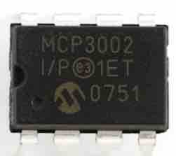
As a way of providing an 10 bit value that represents the analog 'intensity' of the light from the light sensor, this chip offers 2 input and SPI (with data output) pins that can interface with the Raspberry Pi. I will go on more details on how that works in part 2 of this blog. I only need one analog input, so I actually connected the 2 input pins to the same photo resistor. With that, the code reads from the 2 pins and take an simple average. You can use the version of this chip that offers 8 analog inputs (ie MCP3008), but that felt like too much of a waste for this project, so I bought the 2 pin version from Digi-Key.
Thanks to awesome resources on this chip, it was pretty easy to write a little c++ program to have the RPI talking to this chip. Sorry for sounding like a broken record, but there is more on that code in part 2 of this blog.
Small Breadboard
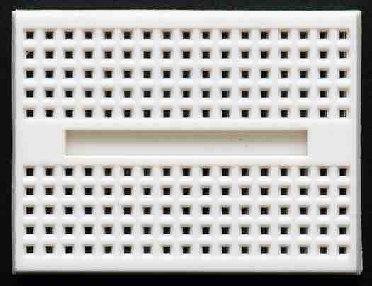
Given my poor dexterity in handling a soldering iron, I rather go for the breadboard whenever possible. :) On that account, I needed a vessel to hold the MCP3002 as well as the Cobbler Plus. These are very easy to find, including the one at the Adafruit shop.
Raspberry Pi GPIO Breakout
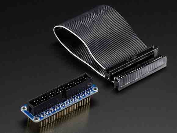
The easiest way to hook the GPIO (aka General Purpose Input/Output) is by using one of these breakouts. The one sold by Adafruit already comes with a 40 pin cable.
Power Strip, Wires, etc
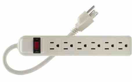
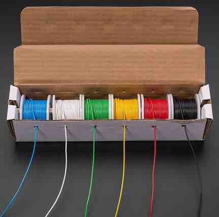
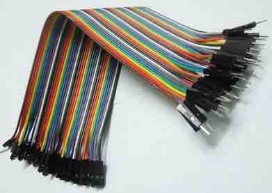
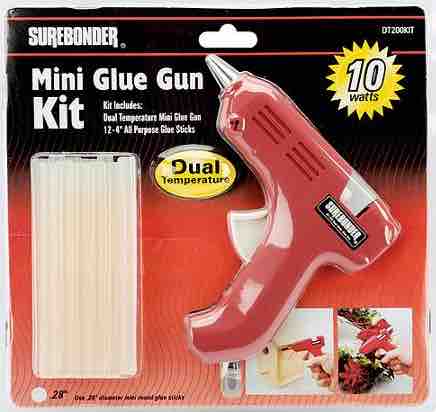
As you can see in the pictures, I connected all the power supplies to a simple power strip. To help myself with the soldering iron phobia, I used a couple of Phantom Yoyo wires to hookup the displays to the breadboard. I also used 22 AWG core wires to daisy chain the power for the led matrix displays, as well as extending the connections from the sensors to the breadboard. To bond the pieces together -- such as the display panels, sensors and breadboard -- I used a simple hot glue gun.
Pictures and Hookup Diagrams
I took a bunch of pictures while doing this project and uploaded them to Flickr. Click here to see them.
Motion and Light Sensors
Led Strip
Led Matrix Display
USB Hub Devices
Comments
comments powered by Disqus